LT PVC Armoured / Un Armoured Power & Control Cables
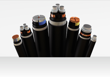
AGL Cables Pvt. Ltd. is a topmost manufacturer of a wide range of Armoured Cables, Armoured Power Cables, Armoured Electrical Cables, PVC Armoured Cables and XLPE Armoured Cables.
- XLPE means cross-linked polyethene or vulcanized polyethene. The basic material is low-density polyethene.
- Polyethene is a thermoplastic material consisting of a long chain of hydrocarbon molecules. At elevated temperatures, these molecules tend to move relative to one another so that the material becomes increasingly deformable and will eventually melt at a temperature around 110°C.
- In the process of rubber, the polyethene molecules can be cross-linked. The process of cross-linking or vulcanization consists of producing chemical bonds at intervals between the long molecular chain to give a ladder effect which prevents slippage between molecules as a result of cross-linking the material becomes heat resistant and does not soften at higher temperatures.
- Further, it has better resistance to stress cracking and good resistance to ageing in hot air. With the change of structure, there is no adverse effect on electrical properties.
CONDUCTOR
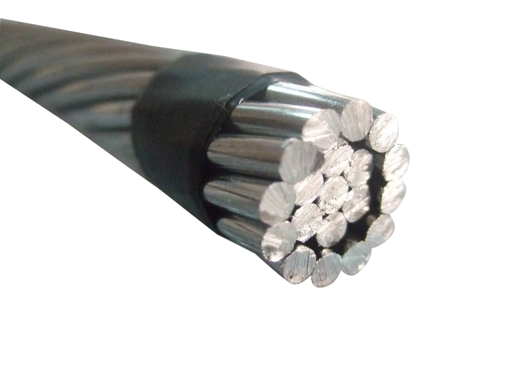
The most acceptable metals are copper and Aluminium due to their higher conductivity & ductility. As Copper has got a higher affinity for sulfur, it corrodes in the atmosphere where sulfur fumes are present. In these conditions, tinned copper should be used. Aluminum oxide film which is always present on the aluminum conductor surface acts as a barrier and protects the Aluminum conductor from corrosion in fumes laden atmosphere.
INSULATION
The PVC covering over the conductor is called insulation and is provided by the extrusion process only. The insulated conductor is called core.I.S.:1554 permits two types of PVC insulation as follows:
- Insulation with type A PVC Compound as per IS: 5831 which is suitable for 70°C continuous operations.
- Insulation with type C PVC Compound as per IS: 5831 which is suitable for 85°C continuous operations.
LAYING UP
The cores are laid up with suitable lay. The final layer always has a right-hand lay i.e. if you look along the cable, the cores move to your right hand.
CONDUCTOR CONSTRUCTION
- The most economical construction for the conductor is a solid conductor i.e. conductor made of one single wire. As the area conductor increases, the solid conductor becomes stiffer and hence difficult to handle in this case stranded construction is adopted.
- Here the conductor is made of a number of strands. This construction provides more flexibility. Where crimping of lugs is required, the conductor has to be of stranded construction only.
- To economies in insulating material, weight, and overall diameter, shaped conductors are employed in bigger-sized cables.
- Here the stranded conductor is shaped into a segment of a circle so that when all the cores are laid, they form a complete circle.
- These segments are identified as 2 Core- 180 degrees, 3 Core- 120 degrees, 4 Core- 90 degrees, 3.5 Core- 100/60 degrees. I.S.1554 permits solid conductor construction up to 10 sq. mm in aluminum and up to 6 sq. mm in copper. It permits the use of shaped conductors for the size from 16sq.mm onwards.
INNER SHEATH
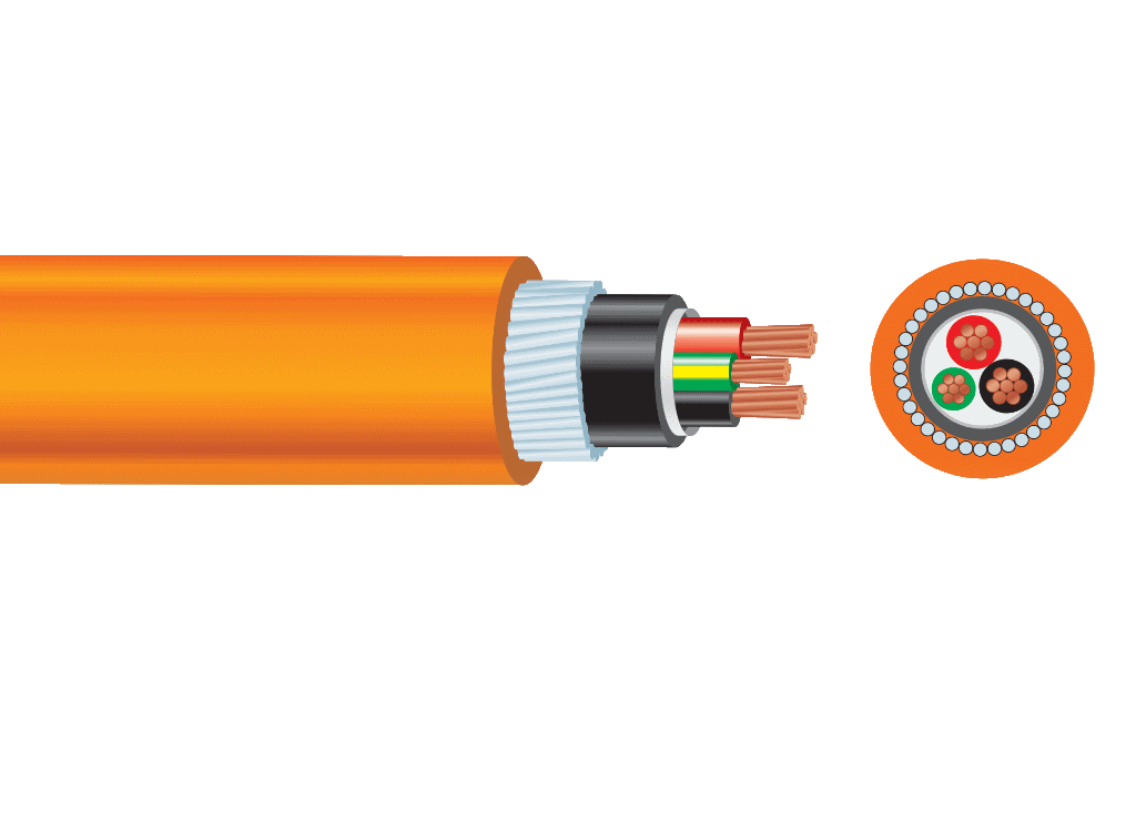
The inner sheath is provided over the laid-up cores. It is provided to give a circular shape to the cable and it provides bedding for the armoring.
I.S. 1554 permits the following two methods of applying the inner sheath of any thermoplastic material i.e. PVC, Polyethylene, etc.
- EXTRUDED INNER SHEATH: Here the inner sheath is provided by extrusion of Thermoplastic over the laid up cores. This type of Innersheath is generally provided in cables having round cores i.e. in control cables and power cables up to 10 sq. mm sizes. This type of inner sheath also acts as a water barrier between cores and the outer sheath. In case of a puncture in the outer sheath, the water cannot reach the cores and hence we recommend that cables for outdoor underground uses should have extruded inner sheath.
- TAPPED INNER SHEATH: Here the inner sheath is provided by wrapping thermoplastic tape over the laid-up cores. It is generally employed in cables having sector-shaped cores i.e. multi-core cables of 16sq.mm and above.
This method saves a process and hence manufacturers always provide this type of inner sheath unless the purchase specifications ask for the extruded inner sheath.
ARMOURING
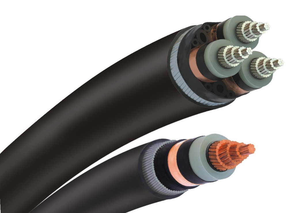
- In the case of armoured cables, generally galvanized steel wire/strip is provided over the inner sheath is multi-core cables and Aluminium Round wire or Aluminium strip over the insulation in single-core cables. It provides mechanical protection inside cores and it carries earth return current in case of a short circuit of a core with armour.
- As per I.S. 1554 (Part-1) 1988, round wire armouring is provided in cable, where the calculated diameter under armour is up to 13 mm. Above this, the armouring is either with round wire or strip of size 4 mm 0.80 mm. As strip construction is economical, the manufactures always provide steel strip armouring unless wire armouring is specially specified.
- In the long run of cables and in the case of mines, round wire armouring is a must, as strip construction provides higher resistance to earth fault current and sometimes this current may not be sufficient to operate the circuit breaker in case of an earth fault.
- In mines, the resistance of the armour in no case should exceed the resistance of the main core by more than 33% for safety reasons. To achieve this, sometimes tinned hard drawn copper wires are required to be used along with galvanized steel wires. Sometimes two layers of Round steel wire or Steel Strip are applied in opposite direction with barrier tape in between are provided to give extra protection.
- In the case of single-core for use in AC circuits, the material for armouring has to be nonmagnetic, as in this case the return current is not passing through the same cable and hence it will not cancel the magnetic lines produced by the current. These magnetic lines which are oscillating in case of AC current will give rise to eddy current in magnetic armouring and hence armouring will become hot, and this may lead to the failure of the cable. Generally hard drawn aluminium wires/strip are used for armouring in this case.
OUTER SHEATH
- The PVC covering the armoring in case of armored cables and over the inner sheath in case of un-armored cables is called an outer sheath.
- I.S. 1554 specifies the nominal and minimum thickness of outer sheath for UN–armored cables and only the minimum thickness of outer sheath for armored cables.
It permits the following types of outer sheath PVC compounds.
- Outer sheath with type ST1 PVC compound as per IS 5831, which is suitable for 70°C continuous operations.
- Outer sheath with type ST2 PVC compound as per IS 5831, which is suitable for 85°C continuous operations.
- PVC has got fire retardant properties due to its halogen content. The fire in the cable gets extinguished immediately on removal of the fire source.
- In modern Power, Chemical, Fertilizer, and Cement plants many PVC cables are bunched in the cable shaft or on cable trays. In case of fire in these cables, the fire becomes self-sustaining.
- Moreover, due to the burning of PVC a dense corrosive smoke is emitted which makes fire fighting very difficult, due to poor visibility and the toxic nature of the smoke. HCL content of the smoke, not only damages other costly equipment lying nearby but also penetrates the RCC and corrodes the steel reinforcement. Due to this, there is an extension to the property.
- To overcome these deficiencies FRLS i.e. Fire Retardant Low Smoke PVC was developed. If required, we can provide Fire Retardant Low Smoke (FRLS) PVC Inner Sheath and/or outer sheath. This PVC compound, apart from meeting the requirements of Type ST2 as per IS-5831, has got better fire retardant properties and it emits lower smoke and acid fumes when it catches fire.

